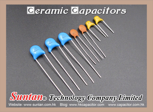
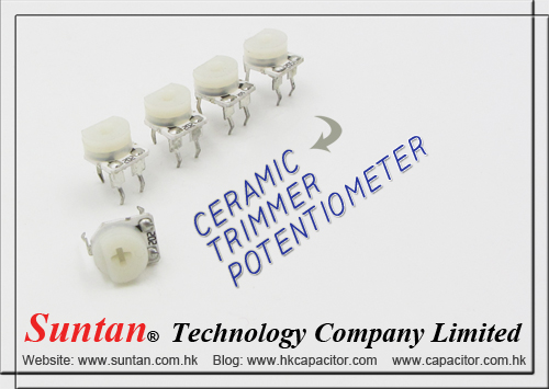
Suntan With Coated Potentiometers and Wire-Wound Potentiometers

Previous blog we talk about Potentiometers by means of construction, they can be divided into 2 groups: coated and wire-wound. Now let us to to know more related details of it.

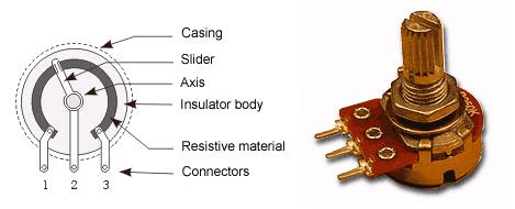
With coated potentiometers, (as shown follow figure), insulator body is coated with a resistive material. There is a conductive slider moving across the resistive layer, increasing the resistance between slider and one end of pot, while decreasing the resistance between slider and the other end of pot.

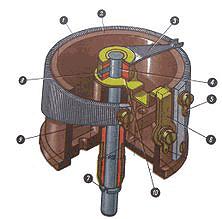
Wire-wound potentiometers are made of conductor wire coiled around insulator body.  There is a slider moving across the wire, increasing the resistance between slider and one end of pot, while decreasing the resistance between slider and the other end of pot. Wire-wound potentiometers are used in devices which require more accuracy in control. They feature higher dissipation than coated pots, and are therefore in high current circuits. Construction of a wire-wound circular potentiometer (as shown follow figure). The resistive element (1) of the shown device is trapezoidal, giving a non-linear relationship between resistance and turn angle. The wiper (3) rotates with the axis (4), providing the changeable resistance between the wiper contact (6) and the fixed contacts (5) and (9). The vertical position of the axis is fixed in the body (2) with the ring (7) (below) and the bolt (8) (above).

Coated pots are much more common. With these, resistance can be linear, logarithmic, inverse-logarithmic or other, depending upon the angle or position of the slider. Most common are linear and logarithmic potentiometers, and the most common applications are radio-receivers, audio amplifiers, and similar devices where pots are used for adjusting the volume, tone, balance, etc..

Suntan How are Ceramic Capacitors constructed? Part 1

Suntan Technology Company Limited
----All Kinds of Capacitors

Dipped Ceramic Capacitors. The simplest ceramic capacitor consists of a square or circular shaped ceramic with electrodes attached (see figure). The capacitance is given by 

where A is the area of the two plates,  is the dielectric permittivity of vacuum, Kd is the dielectric's dielectric constant and d is the distance between the two plates.http://www.capacitors.hk/Ceramic-Capacitors/

Suntan Monolithic/Multilayer Ceramic Capacitors

Suntan Technology Company Limited
----All Kinds of Capacitors

MLC capacitors are marvels of modern material science. Manufacturing MLC capacitors is considerably more complicated than manufacturing dipped ceramic capacitors. First, the base ceramic material is mixed with a binder and fashioned into thin sheets. Electrodes are painted onto one side of the sheets using a paint that consists of a liquid binder with fine metal particles in suspension. The metals that are used include gold, palladium, platinum, and silver alloys. The reason for using these metals is that when the base ceramic is fired, oxygen is required for the ceramic proper to form. If one uses a metal such as iron, for example, it would oxidize completely during the firing process.Precious metals do not have this problem, but is a major cost component of monolithic ceramic capacitors. However, recently some manufacturers have reported using nickel and copper for the electrodes. This promises to reduce the cost of the raw materials, but at the expense of more elaborate manufacturing processes.

Once the ink is dry, the sheets are stacked on top of each other. The painted electrodes are arranged so that alternate electrodes exit from opposite ends. The top and bottom most layers do not have painted electrodes. The laminated layers are then compressed and fired, which sinters them into one monolithic structure.

Next, the ends are terminated, often using silver. For leaded capacitors, wires are attached, and finally the capacitor is encapsulated in plastic and marked. In the case of chip capacitors, the silver end terminations are covered with tin to aid soldering. The whole capacitor may be covered with lacquer.

Construction Details of A Wet Aluminum Electrolytic Capacitor - Production Process

Suntan Technology Company Limited
---All Kinds of Capacitors

Aluminum electrolytic capacitors are comprised of anode and cathode plates separated by an absorbent spacer. As shown in Figure below, metal tabs are attached to the anode and cathode plates, and the assembly is wound into a cylindrical section. The tabs are welded to aluminum terminals installed in a header (top). The section-header assembly is immersed in a bath of hot capacitor electrolyte (significantly different from the formation process electrolyte). In what is called the impregnation process, a vacuum is applied to the electrolyte and sections, causing electrolyte to be drawn into the sections, thoroughly wetting the sections. The sections are placed in aluminum cans, and the headers are sealed to the cans. The capacitor units are slowly brought up to maximum rated voltage at maximum rated temperature during the aging process. The aging process grows oxide on areas on the anode foil which have an insufficient oxide barrier, such as slit edges and places which have been cracked during the winding operation. Inspections and tests occur at several stages of the production process.

For more details please check : http://www.capacitors.hk/Aluminum-Electrolytic-Capacitors/

Suntan Ceramic Trimmer Potentiometer

Suntan Technology Company Limited
----All Kinds of Capacitors

Ceramic Trimmer Potentiometer Features

  1. 6mm Round/ Single-Turn/ Cermet Industrial/ Open Frame
  2. Cross slot adjustment options
  3. Horiontal andvertical mounting styles
  4. Dust resistant/ splash resistant covers
  5. PC board stand-offs and retention feature
  6. Front and top adjust styles

Ceramic Trimmer Potentiometer Electrical Characteristics

  1. Standard Resistance Range 100Ω to 1meg ohm
  2. Resistance Tolerance ±20% (TK±25%)
  3. Adjustment Angle 240°C ± 20°C
  4. Residual Resistance ≤500Ω, 10Ω>500Ω, 2% 

Ceramic Trimmer Potentiometer Pictures

Su Suntan Analyze How Capacitors Work

Suntan Technology Company Limited
---All kinds of Capacitors


In a way, a capacitor is a little like a battery. Although they work in completely different ways, capacitors and batteries both store electrical energy. If you have read How Batteries Work, then you know that a battery has two terminals. Inside the battery, chemical reactions produce electrons on one terminal and absorb electrons on the other terminal. A capacitor is much simpler than a battery, as it can't produce new electrons -- it only stores them.

In this article, we'll learn exactly what a capacitor is, what it does and how it's used in electronics. We'll also look at the history of the capacitor and how several people helped shape its progress.

Inside the capacitor, the terminals connect to two metal plates separated by a non-conducting substance, or dielectric. You can easily make a capacitor from two pieces of aluminum foil and a piece of paper. It won't be a particularly good capacitor in terms of its storage capacity, but it will work.

In theory, the dielectric can be any non-conductive substance. However, for practical applications, specific materials are used that best suit the capacitor's function. Mica, ceramic, cellulose, porcelain, Mylar, Teflon and even air are some of the non-conductive materials used. The dielectric dictates what kind of capacitor it is and for what it is best suited. Depending on the size and type of dielectric, some capacitors are better for high frequency uses, while some are better for high voltage applications. Capacitors can be manufactured to serve any purpose, from the smallest plastic capacitor in your calculator, to an ultra capacitor that can power a commuter bus. NASA uses glass capacitors to help wake up the space shuttle's circuitry and help deploy space probes. Here are some of the various types of capacitors and how they are used.

  • Air - Often used in radio tuning circuits
  • Mylar - Most commonly used for timer circuits like clocks, alarms and counters
  • Glass - Good for high voltage applications
  • Ceramic - Used for high frequency purposes like antennas, X-ray and MRI machines
  • Super capacitor - Powers electric and hybrid cars

In the next section, we'll take a closer look at exactly how capacitors work.

Su Suntan Electrochemical Type Capacitors

Suntan Technology Company Limited
---All kinds of Capacitors

Aluminum is used for the electrodes by using a thin oxidization membrane.

Large values of capacitance can be obtained in comparison with the size of the capacitor, because the dielectric used is very thin.

The most important characteristic of electrolytic capacitors is that they have polarity. They have a positive and a negative electrode.[Polarised] This means that it is very important which way round they are connected. If the capacitor is subjected to voltage exceeding its working voltage, or if it is connected with incorrect polarity, it may burst. It is extremely dangerous, because it can quite literally explode. Make absolutely no mistakes.

Generally, in the circuit diagram, the positive side is indicated by a "+" (plus) symbol.

Electrolytic capacitors range in value from about 1µF to thousands of µF. Mainly this type of capacitor is used as a ripple filter in a power supply circuit, or as a filter to bypass low frequency signals, etc. Because this type of capacitor is comparatively similar to the nature of a coil in construction, it isn't possible to use for high-frequency circuits. (It is said that the frequency characteristic is bad.)

The photograph on the left is an example of the different values of electrolytic capacitors in which the capacitance and voltage differ.

From the left to right:

  • 1µF (50V) [diameter 5 mm, high 12 mm]
  • 47µF (16V) [diameter 6 mm, high 5 mm]
  • 100µF (25V) [diameter 5 mm, high 11 mm]
  • 220µF (25V) [diameter 8 mm, high 12 mm]
  • 1000µF (50V) [diameter 18 mm, high 40 mm]

The size of the capacitor sometimes depends on the manufacturer. So the sizes shown here on this page are just examples.

In the photograph to the right, the mark indicating the negative lead of the component can be seen. You need to pay attention to the polarity indication so as not to make a mistake when you assemble the circuit.

Su Suntan Capacitors

Suntan Technology Company Limited
---All kinds of Capacitors

  • The capacitor's function is to store electricity, or electrical energy.
  • The capacitor also functions as a filter, passing alternating current (AC), and blocking direct current (DC).
  • This symbol is used to indicate a capacitor in a circuit diagram.

The capacitor is constructed with two electrode plates facing eachother, but separated by an insulator.

When DC voltage is applied to the capacitor, an electric charge is stored on each electrode. While the capacitor is charging up, current flows. The current will stop flowing when the capacitor has fully charged.

When a circuit tester, such as an analog meter set to measure resistance, is connected to a 10 microfarad (µF) electrolytic capacitor, a current will flow, but only for a moment. You can confirm that the meter's needle moves off of zero, but returns to zero right away.

When you connect the meter's probes to the capacitor in reverse, you will note that current once again flows for a moment. Once again, when the capacitor has fully charged, the current stops flowing. So the capacitor can be used as a filter that blocks DC current. (A "DC cut" filter.)

However, in the case of alternating current, the current will be allowed to pass. Alternating current is similar to repeatedly switching the test meter's probes back and forth on the capacitor. Current flows every time the probes are switched.

The value of a capacitor (the capacitance), is designated in units called the Farad ( F ).

The capacitance of a capacitor is generally very small, so units such as the microfarad ( 10-6F ), nanofarad ( 10-9F ), and picofarad (10-12F ) are used.

Recently, an new capacitor with very high capacitance has been developed. The Electric Double Layer capacitor has capacitance designated in Farad units. These are known as "Super Capacitors."

Sometimes, a three-digit code is used to indicate the value of a capacitor. There are two ways in which the capacitance can be written. One uses letters and numbers, the other uses only numbers. In either case, there are only three characters used. [10n] and [103] denote the same value of capacitance. The method used differs depending on the capacitor supplier. In the case that the value is displayed with the three-digit code, the 1st and 2nd digits from the left show the 1st figure and the 2nd figure, and the 3rd digit is a multiplier which determines how many zeros are to be added to the capacitance. Picofarad ( pF ) units are written this way.

For example, when the code is [103], it indicates 10 x 103, or 10,000pF = 10 nanofarad( nF ) = 0.01 microfarad( µF ).

If the code happened to be [224], it would be 22 x 104 = or 220,000pF = 220nF = 0.22µF.

Values under 100pF are displayed with 2 digits only. For example, 47 would be 47pF.

The capacitor has an insulator( the dielectric ) between 2 sheets of electrodes. Different kinds of capacitors use different materials for the dielectric.

Su Suntan Tantalum Bead Capacitors

Suntan Technology Company Limited
---All kinds of Capacitors

Tantalum bead capacitors are polarised and have low voltage ratings like electrolytic capacitors. They are expensive but very small, so they are used where a large capacitance is needed in a small size.

Modern tantalum bead capacitors are printed with their capacitance, voltage and polarity in full. However older ones use a colour-code system which has two stripes (for the two digits) and a spot of colour for the number of zeros to give the value in µF. The standard colour code is used, but for the spot, grey is used to mean × 0.01 and white means × 0.1 so that values of less than 10µF can be shown. A third colour stripe near the leads shows the voltage (yellow 6.3V, black 10V, green 16V, blue 20V, grey 25V, white 30V, pink 35V). The positive (+) lead is to the right when the spot is facing you: 'when the spot is in sight, the positive is to the right'. 

  • For example:   blue, grey, black spot   means 68µF
  • For example:   blue, grey, white spot   means 6.8µF
  • For example:   blue, grey, grey spot   means 0.68µF


Su Suntan Capacitance

Suntan Technology Company Limited
---All kinds of Capacitors

This is a measure of a capacitor's ability to store charge. A large capacitance means that more charge can be stored. Capacitance is measured in farads, symbol F. However 1F is very large, so prefixes are used to show the smaller values.

Three prefixes (multipliers) are used, µ (micro), n (nano) and p (pico):

  • µ means 10-6 (millionth), so 1000000µF = 1F
  • n means 10-9 (thousand-millionth), so 1000nF = 1µF
  • p means 10-12 (million-millionth), so 1000pF = 1nF

Capacitor values can be very difficult to find because there are many types of capacitor with different labelling systems!

There are many types of capacitor but they can be split into two groups, polarised and unpolarised. Each group has its own circuit symbol.