Suntan's Slogan:All Kinds of Capacitors
Posted
May 8,2012  Comments(0)
Comments(0) Comments(0) Comments(0)
Suntan Technology Company Limited
----All Kinds of Capacitors
Suntan New Sample box is coming up soon.
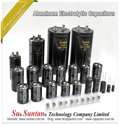
Comments(0) Suntan Technology Company Limited
----All Kinds of Capacitors
On capacitors that are large enough (e.g. electrolytic capacitors) the capacity and working voltage are printed on the body without encoding. Sometimes the markings also include the maximum working temperature, manufacturer's name and other information.
Smaller capacitors use a shorthand notation, to display all the relevant information in the limited space. The most commonly used format is: XYZ J/K/M VOLTS V, where XYZ represents the capacitance (calculated as XY×10Z pF), the letters J, K or M indicate the tolerance (±5%, ±10% and ±20% respectively) and VOLTS V represents the working voltage.
Polarised capacitors, for which one electrode must always be positive relative to the other, have clear polarity markings, usually a stripe or a "-" sign on the side of the negative electrode. Also, the negative lead is usually shorter.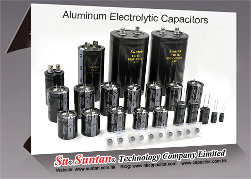
Comments(0) Suntan Technology Company Limited
---All Kinds of Capacitors
This is an effective resistance that is used to describe the resistive parts of the impedance of certain electronic components. The theoretical treatment of devices such as capacitors and inductors tends to assume they are ideal or "perfect" devices, contributing only capacitance or inductance to the circuit. However, all (non-superconducting) physical devices are constructed of materials with nonzero electrical resistance, which means that all real-world components contain some resistance in addition to their other properties. A low ESR capacitor typically has an ESR of 0.01 Ω. Low values are preferred for high-current, pulse applications. Low ESR capacitors have the capability to deliver huge currents into short circuits, which can be dangerous.
For capacitors, ESR takes into account the internal lead and plate resistances and other factors. An easy way to deal with these inherent resistances in circuit analysis is to express each real capacitor as a combination of an ideal component and a small resistor in series, the resistor having a value equal to the resistance of the physical device.
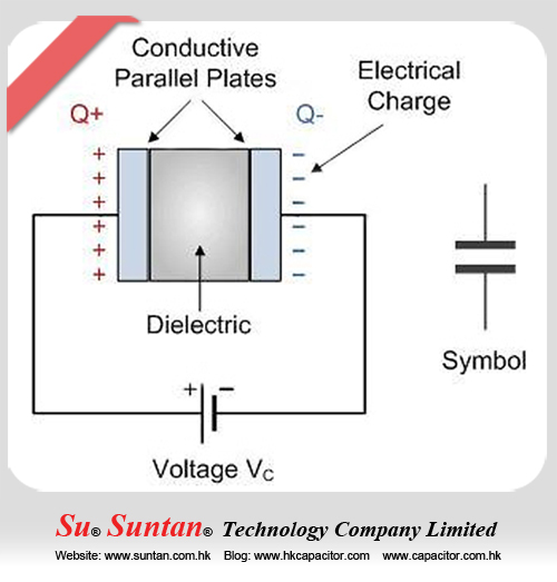
Comments(0) When used in a direct-current or DC circuit, a capacitor blocks the flow of current through it, but when it is connected to an alternating-current or AC circuit, the current appears to pass straight through it with little or no resistance. If a DC voltage is applied to the capacitors conductive plates, a current flows charging up the plates with electrons giving one plate a positive charge and the other plate an equal and opposite negative charge. This flow of electrons to the plates is known as the Charging Current and continues to flow until the voltage across both plates (and hence the capacitor) is equal to the applied voltage VC At this point the capacitor is said to be fully charged with electrons with the strength of this charging current at its maximum when the plates are fully discharged and slowly reduces in value to zero as the plates charge up to a potential difference equal to the applied supply voltage and this is show below.
More details please check : http://www.suntan.com.hk/
Comments(0) Suntan Technology Company Limited
----All Kinds of Capacitors
When clouds drift through the sky, ice particles inside them rub against the air and gain static electrical charges—in just the same way that a balloon gets charged up when you rub it on your jumper. The top of a cloud becomes positively charged when smaller ice particles swirl upward (1); the bottom of a cloud becomes negatively charged when the heavier ice particles gather lower down (2). The separation of positive and negative charges in a cloud makes a kind of moving capacitor!
As a cloud floats along, the electric charge it contains affects things on the ground beneath it. The huge negative charge at the bottom of the cloud repels negative charge away from it, so the ground effectively becomes positively charged (3). The separation of charge between the bottom of the cloud and the ground beneath means that this area of the atmosphere is also, effectively, a capacitor.
Over time, enormous electrical charges can build up inside clouds. If the charge is really big, the cloud contains an enormous amount of electrical potential energy (it has a really high voltage). When the voltage reaches a certain level (sometimes several hundred million volts), the air is transformed from being an insulator into a conductor, and electricity will flow through it as though it were a metal wire, creating a giant spark better known as a bolt of lightning (4). The cloud behaves like a flash gun in a camera: the huge electrical energy stored in its "capacitor" is discharged in an instant and converted into a flash of light.
Comments(0) Suntan Technology Company Limited
----All Kinds of Capacitors
The size of a capacitor is measured in units called farads (F), named for English electrical pioneer Michael Faraday (1791–1867). One farad is a huge amount of capacitance so, in practice, most of the capacitors we come across are just fractions of a farad—typically microfarads (thousandths of a farad, written μF), nanofarads (thousand-millionths of a farad written nF), and picofarads (million millionths of a farad, written pF). Supercapacitors store far bigger charges, sometimes rated in thousands of farads.
Comments(0) Suntan Technology Company Limited
----All Kinds of Capacitors
When reading schematics, repairing radios and buying capacitors, you often must convert between uF, nF and pF.
Paper and electrolytic capacitors are usually expressed in terms of uF (microfarads). Short forms for micro farad include uF, mfd, MFD, MF and UF. Mica capacitors are usually expressed in terms of pF (micromicrofarads) (picofarads).
Short forms for micromicrofarads include pF, mmfd, MMFD, MMF, uuF and PF. A pF is one-millionth of a uF. In between a pF and a uF is a nF which is one-one thousands of a uF. Converting back and forth between uF, nF and pF can be confusing with all those darn decimal points to worry about. Below is a uF - nF- pF conversion chart.
| uF/ MFD | nF | pF/ MMFD |
| 1uF / MFD | 1000nF | 1000000pF |
| 0.82uF / MFD | 820nF | 820000pF |
| 0.8uF / MFD | 800nF | 800000pF |
| 0.7uF / MFD | 700nF | 700000pF |
| 0.68uF / MFD | 680nF | 680000pF |
| 0.6uF / MFD | 600nF | 600000pF |
| 0.56uF / MFD | 560nF | 560000pF |
| 0.5uF / MFD | 500nF | 500000pF |
| 0.47uF / MFD | 470nF | 470000pF |
| 0.4uF / MFD | 400nF | 400000pF |
| 0.39uF / MFD | 390nF | 390000pF |
| 0.33uF / MFD | 330nF | 330000pF |
| 0.3uF / MFD | 300nF | 300000pF |
| 0.27uF / MFD | 270nF | 270000pF |
| 0.25uF / MFD | 250nF | 250000pF |
| 0.22uF / MFD | 220nF | 220000pF |
| 0.2uF / MFD | 200nF | 200000pF |
| 0.18uF / MFD | 180nF | 180000pF |
| 0.15uF / MFD | 150nF | 150000pF |
| 0.12uF / MFD | 120nF | 120000pF |
| 0.1uF / MFD | 100nF | 100000pF |
| 0.082uF / MFD | 82nF | 82000pF |
| 0.08uF / MFD | 80nF | 80000pF |
| 0.07uF / MFD | 70nF | 70000pF |
| 0.068uF / MFD | 68nF | 68000pF |
| 0.06uF / MFD | 60nF | 60000pF |
| 0.056uF / MFD | 56nF | 56000pF |
| 0.05uF / MFD | 50nF | 50000pF |
| 0.047uF / MFD | 47nF | 47000pF |
| 0.04uF / MFD | 40nF | 40000pF |
| 0.039uF / MFD | 39nF | 39000pF |
| 0.033uF / MFD | 33nF | 33000pF |
| 0.03uF / MFD | 30nF | 30000pF |
| 0.027uF / MFD | 27nF | 27000pF |
| 0.025uF / MFD | 25nF | 25000pF |
| 0.022uF / MFD | 22nF | 22000pF |
| 0.02uF / MFD | 20nF | 20000pF |
| 0.018uF / MFD | 18nF | 18000pF |
| 0.015uF / MFD | 15nF | 15000pF |
| 0.012uF / MFD | 12nF | 12000pF |
| 0.01uF / MFD | 10nF | 10000pF |
| 0.0082uF / MFD | 8.2nF | 8200pF |
| 0.008uF / MFD | 8nF | 8000pF |
| 0.007uF / MFD | 7nF | 7000pF |
| 0.0068uF / MFD | 6.8nF | 6800pF |
| 0.006uF / MFD | 6nF | 6000pF |
| 0.0056uF / MFD | 5.6nF | 5600pF |
| 0.005uF / MFD | 5nF | 5000pF |
| 0.0047uF / MFD | 4.7nF | 4700pF |
| 0.004uF / MFD | 4nF | 4000pF |
| 0.0039uF / MFD | 3.9nF | 3900pF |
| 0.0033uF / MFD | 3.3nF | 3300pF |
| 0.003uF / MFD | 3nF | 3000pF |
| 0.0027uF / MFD | 2.7nF | 2700pF |
| 0.0025uF / MFD | 2.5nF | 2500pF |
| 0.0022uF / MFD | 2.2nF | 2200pF |
| 0.002uF / MFD | 2nF | 2000pF |
| 0.0018uF / MFD | 1.8nF | 1800pF |
| 0.0015uF / MFD | 1.5nF | 1500pF |
| 0.0012uF / MFD | 1.2nF | 1200pF |
| 0.001uF / MFD | 1nF | 1000pF |
| 0.00082uF / MFD | 0.82nF | 820pF |
| 0.0008uF / MFD | 0.8nF | 800pF |
| 0.0007uF / MFD | 0.7nF | 700pF |
| 0.00068uF / MFD | 0.68nF | 680pF |
| 0.0006uF / MFD | 0.6nF | 600pF |
| 0.00056uF / MFD | 0.56nF | 560pF |
| 0.0005uF / MFD | 0.5nF | 500pF |
| 0.00047uF / MFD | 0.47nF | 470pF |
| 0.0004uF / MFD | 0.4nF | 400pF |
| 0.00039uF / MFD | 0.39nF | 390pF |
| 0.00033uF / MFD | 0.33nF | 330pF |
| 0.0003uF / MFD | 0.3nF | 300pF |
| 0.00027uF / MFD | 0.27nF | 270pF |
| 0.00025uF / MFD | 0.25nF | 250pF |
| 0.00022uF / MFD | 0.22nF | 220pF |
| 0.0002uF / MFD | 0.2nF | 200pF |
| 0.00018uF / MFD | 0.18nF | 180pF |
| 0.00015uF / MFD | 0.15nF | 150pF |
| 0.00012uF / MFD | 0.12nF | 120pF |
| 0.0001uF / MFD | 0.1nF | 100pF |
| 0.000082uF / MFD | 0.082nF | 82pF |
| 0.00008uF / MFD | 0.08nF | 80pF |
| 0.00007uF / MFD | 0.07nF | 70pF |
| 0.000068uF / MFD | 0.068nF | 68pF |
| 0.00006uF / MFD | 0.06nF | 60pF |
| 0.000056uF / MFD | 0.056nF | 56pF |
| 0.00005uF / MFD | 0.05nF | 50pF |
| 0.000047uF / MFD | 0.047nF | 47pF |
| 0.00004uF / MFD | 0.04nF | 40pF |
| 0.000039uF / MFD | 0.039nF | 39pF |
| 0.000033uF / MFD | 0.033nF | 33pF |
| 0.00003uF / MFD | 0.03nF | 30pF |
| 0.000027uF / MFD | 0.027nF | 27pF |
| 0.000025uF / MFD | 0.025nF | 25pF |
| 0.000022uF / MFD | 0.022nF | 22pF |
| 0.00002uF / MFD | 0.02nF | 20pF |
| 0.000018uF / MFD | 0.02nF | 20pF |
| 0.000015uF / MFD | 0.015nF | 15pF |
| 0.000012uF / MFD | 0.012nF | 12pF |
| 0.00001uF / MFD | 0.01nF | 10pF |
| 0.0000082uF / MFD | 0.0082nF | 8.2pF |
| 0.000008uF / MFD | 0.008nF | 8pF |
| 0.000007uF / MFD | 0.007nF | 7pF |
| 0.0000068uF / MFD | 0.0068nF | 6.8pF |
| 0.000006uF / MFD | 0.006nF | 6pF |
| 0.0000056uF / MFD | 0.0056nF | 5.6pF |
| 0.000005uF / MFD | 0.005nF | 5pF |
| 0.0000047uF / MFD | 0.0047nF | 4.7pF |
| 0.000004uF / MFD | 0.004nF | 4pF |
| 0.0000039uF / MFD | 0.0039nF | 3.9pF |
| 0.0000033uF / MFD | 0.0033nF | 3.3pF |
| 0.000003uF / MFD | 0.003nF | 3pF |
| 0.0000027uF / MFD | 0.0027nF | 2.7pF |
| 0.0000025uF / MFD | 0.0025nF | 2.5pF |
| 0.0000022uF / MFD | 0.0022nF | 2.2pF |
| 0.000002uF / MFD | 0.002nF | 2pF |
| 0.0000018uF / MFD | 0.0018nF | 1.8pF |
| 0.0000015uF / MFD | 0.0015nF | 1.5pF |
| 0.0000012uF / MFD | 0.0012nF | 1.2pF |
| 0.000001uF / MFD | 0.001nF | 1pF |
+/-5%(J), +/-10%(K), +/-20%(M)The letter after the marking often indicates the tolerance.
Example:101K would be 100pf, +/-10%
When You Are Tired, Do You Get a Headache Converting Picofarads to Microfarads?
Maybe this will help you.
| 4.7 mmf or pf | = | .0000047 mf |
| 47 mmf or pf | = | .000047 mf |
| 470 mmf or pf | = | .00047 mf |
| 4,700 mmf or pf | = | .0047 mf |
| 47,000 mmf or pf | = | .047 mf |
| 470,000 mmf or pf | = | .47 mf |
Comments(0) Suntan Technology Company Limited
----All Kinds of Capacitors
Desalination could dramatically help the looming shortage with water. The problem is the membrane.
Right now, desalinting seawater largely revolves around pressurizing water and forcing it through a membrane to purify it. The process takes a lot of energy and hence a lot of cost. Desalinating seawater can cost as much as 50 cents a liter.
A collection of private companies and research institutes in Spain have begun to experiment with capacitive deionization for purifying seawater. In this, two electrodes would be placed in a tank. The ions (i.e., salt particles) would be drawn to one electrode. The ions would absorb the ions, which could then be released in a regeneration cycle. Capacitive purification was considered in the past, but the materials were too expensive. So who knows, it might work now.
Expect to see a number of desalination come to the fore in the next few years. Policy makers and the public love the idea and areas of Australia, Africa and China are already suffering through prolonged droughts.
Some of the more interesting ideas out there:
Porifera: A spin-out from Lawrence Livermore National Labs, the company wants to make a desalination membrane out of carbon nanotubes. The company claims it won’t take much energy to purify water in this way and the membrane can’t get fouled. Salt and other bad stuff can’t fit through the pore/openings in the nanotubes.
NanoH2O: Grew out of a research project at UCLA and so far has raised $20 million in two rounds. It has a membrane embedded with nanoparticles that repels salts and lets water pass. By exploiting chemical attraction, NanoH2O reduces the amount of mechanical-induced pressure required for reverse osmosis: The company claims it can process 70 percent more water with 20 percent less power than conventional reverse osmosis plants.
Quos: A highly secretive Chicago company founded by Chinbay Fan and funded by Khosla Ventures. One thing Quos can’t keep secret: patent applications for a system that desalinates and purifies with graphite porous electrodes.
“The apparatus is capable of removing ionized and non-ionized organic compounds, inorganic ions, particulates and bacteria from wastewater streams in a single unit to produce potable water. Porous carbon-based electrodes function as impurities filters to remove particulate matter, such as ash, sand and high molecular weight compounds, as electrodes to concentrate and remove ionic species, and as adsorbents to remove organic materials and bacteria from the wastewater stream,” says patent application 11/724534.
Stonybrook Purification: It has created a thin, fibrous scaffold for reverse osmosis membranes that increases water flow to the reverse osmosis membrane. The company, out of SUNY Stony Brook, also has its own reverse osmosis membrane.
Tel: (852) 8202 8782
Fax: (852) 8208 6246
Email: sales@suntan.com.hk
Website: www.suntan.com.hk
Teams: Suntan Teams
YouTube: Subscribe to our YouTube
WhatsApp: Chat with us on WhatsApp